
In this post I'll walk you through the circuit I'll use for my ultrasonic navigation device introduced here.
The most important part of the circuit is that relative to the motor. In fact connecting the ultrasonic sensor to the Arduino is absolutely trivial, all connections are direct.
I am being heavily inspired by this page for the design of the circuit, given that I am completely new to electronics. But the article assumes that the reader has already a basic understanding of what's going on, so that many details are left out about the working of the circuit, and why certain choices are made.
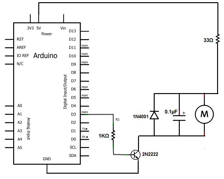 |
| Image taken from learning about electronics |
In this post, I try to make some of that explicit.
A little warning: my knowledge of electronics entirely comes from my trying to reverse-engineer that circuit, and actually stops there. So there could be any number of errors and/or inaccuracies in this post. If you know your way around electronics, please correct me if I'm wrong. If you don't, take everything that follows with a grain of salt.
OK, let's begin.
Delivering the right current and voltage to the motor
We want to drive the vibration motor. We want not only to make it vibrate, but also to control its vibration. We need to deliver to the motor a maximum of 75 mA. The Arduino 5V pin can deliver current in that range no problem, but we would have no control on its modulation via programming. The motor would just vibrate continuously as long as the Arduino was connected to a battery. We do have control on the data pins, but they can only deliver a maximum of 40 mA, meaning that getting around that value you actually start damaging your board. It is much wiser not to let this pin directly deliver the needed current to the motor. So, how to deliver the current and still retain control over the motor's vibration?The answer is: with a transistor.
The way I think about the transistor is a pipe with a door in it, that can be opened or closed, and everything in between. You can vary the amount of current flowing through the pipe by controlling the door. To control the door it takes another source of current, but if you spend x current to open the door, the amount of current flowing through the pipe can be up to 50-100 times x (for the transistor I'll be using).
A transistor has three pins, called Collector, Emitter and Base. The pipe is the passage from the Emitter to the Collector pin, and the door is controlled by the Base pin.
Our data pin can really make good use of a transistor. In fact, the data pin can drive with very little current the door in the transistor, and so control with it a great amount of current (up to 50-100 times) flowing through the Collector-Emitter pipe. This current will come from the 5V pin paired with an appropriate resistor, whereas the door-driving current will come from a data pin and its resistor. Remember that you need a voltage and a resistance to make a current.
Now with some easy mathematics we can figure out the resistors we need for the 5V pin and the data pin so that the motor gets the right amount of controllable current. Also, as the motor needs a voltage of maximum 3.8V, we have to choose our resistor at the 5V pin accordingly. In fact, when resistors are in series, a voltage drop happens across each resistor depending on the contribution of each resistor to the overall resistance. The motor is a 75Ohm resistor. In the tutorial I linked at the beginning of the post, a 33Ohm resistor is used at the 5V pin. Doing the calculations, a 33Ohm resistor would drop the Voltage to more or less 3.5V, which is in the motor range, and together with the motor resistance would cause a current of 5V/(33+108)Ohm = 46mA more or less. Which is below the rated current for the motor. Neat.
Now for the data pin. I am going to use a 5000Ohm resistor here, and I'll explain the reason in a moment.
We will be using Pulse Width Modulation at the data pin. I won't give you the details, but thanks to the PWM we can simulate an analog signal, and we can modulate the voltage from the pin by manipulating the PWM duty cycle. So for example, with a duty cycle of 10%, we would have a voltage of 5V*10%= 0.5V, which divided by the data pin resistance would give a 0.1 mA of current to the Base pin of the transistor. It's clear that by changing the duty cycle percentages we can modify the amount of current going to the Base pin of the transistor, and thus the amount of current flowing through the Collector-Emitter pins in the transistor, and thus the amount of current flowing through the motor. In case of a 100% duty cycle, we would have observed more or less 1 mA*100= 100mA of current to the motor, if that current was available. In reality, as we calculated before, there are only 46mA available from the 5V pin branch. This means that that's the maximum current we can deliver. It also means that our range of usable duty cycles will be from 0% to 46%, as going further than that we are just going to deliver 46mA top, whatever duty cycle we choose.
Making sure that the motor doesn't destroy our Arduino
Thanks to the back-electromotive force, or back-emf, the motor would be able to fry our Arduino every time a sufficiently sudden decrease in current to the motor happened. Like every time we ceased feeding current to it to stop its vibration. But we can prevent that using a diode. A reverse biased diode in parallel doesn't conduct current when the current is flowing in the correct direction. Normally, it is like it's not even there. But if the motor produces an inverse voltage and sends current back, the diode will short-circuit it so that the current doesn't reach the Arduino from the wrong way.
Also, the motor can produce high frequency electrical noise that can affect the functioning of other electronics component. To prevent that we can use a small capacitor, which filters out the high frequency noise. That's the reason for the 0.1 microFarads capacitor.
Conclusion
Once we have the motor circuit, figuring out the rest is easy. In the complete circuit for this project, the motor circuit is doubled as we have two motors, and the connections to the ultrasonic sensors are to be added. One motor circuit draws more or less 50mA, 5V/(33+75)Ohm, and one ultrasonic sensor needs 15mA. Summing up, the Arduino will have to deliver 50*2 + 15*2 = 130mA, which is well below the limit of 400-500 mA that the Arduino can deliver.
In the next post I will actually implement the circuit, and program the Arduino.
I'll keep you posted!
I'll keep you posted!
No comments:
Post a Comment